Motivation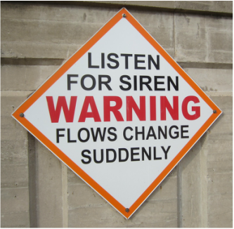
Eagle Creek Renewable Energy operates a hydroelectric plant in Rockton, IL which is supplied via a power canal (channel) with water from the Rock River. The canal is approximately 4,000 feet in length and controlled through five Tainter type gates at the head and two sets of Wicket gates and a Sluice gate at the terminus at the power plant.
The canal passes through portions of the town of Rockton and over-topping is a concern, especially when a utility trip causes both hydroelectric units to shut off simultaneously. The term utility trip is used to describe any anomaly in the electrical system or grid connected to the powerhouse. A trip may be caused by anything from a downed telephone pole, to short-circuiting of old equipment, to unpredictable surges in the grid, to a squirrel getting caught in a transformer. When the hydroelectric units sense something is wrong in the system due to a utility trip, they automatically shut themselves off. In order to prevent damage to the generators, the wicket gates controlling inflow to the turbines also close automatically immediately after a utility trip. These gates close completely, allowing no outflow from the canal through the powerhouse. Under current conditions head gates are controlled individually by electric motors, and need to be operated by personnel on site. In the event of a utility trip, the head gates are unaffected, and will remain open the same height unless manually lowered. As a result, inflow remains nearly constant after a utility trip.. A utility trip event will cause the canal to fill rapidly. Water level will continue to rise until the head gates are closed to restrict inflow, the wicket gates are opened to allow accumulated water to drain, or over-topping occurs. There is a small sluice gate next to the powerhouse at the end of the canal (used to pass logs and other debris around the powerhouse), but outflow through this gate is negligible compared to the large inflow at the head gates. The canal itself only has around one foot of freeboard. Freeboard refers to the vertical distance from the waterline to top of the riverbank. As shown in the picture at the top of the page, the banks along the canal are not built up very high. This means that a relatively small change in water level can cause the channel to overflow. When such an event does occur, there is a very short period of time between the units tripping offline (gates closing at the powerhouse) and the canal over-topping at some location. A potential failure mode analysis (PFMA) of the Rockton hydroelectric project conducted in October 2010 identified 5 potential failure modes. Of these failure modes, only powerhouse trips was deemed category I or I/II, which represent the most severe threats due to failure. The PFMA defines utility trips as events where the “powerhouse trips offline when elevation at powerhouse reaches a pre-determined elevation, leading to a sudden increase of water level in the canal, leading to the over-topping the the dike, resulting in a sudden release of water.” Due to the nature of the canal, there is not a large window of opportunity after a utility trip in which to react. Because of this, ECRE employs an operator living nearby to be on call 24 hours a day. He is alerted when a utility trip occurs, and is responsible for getting to the powerhouse, diagnosing and fixing the problem, restarting the generators, and opening the wicket gates as soon as possible. The unpredictability of utility trips means he has to be able to preform these duties at any time of the day or night. Failure by the operator to react in time and adjust canal gates will result in flooding part of the nearby town of Rockton. |
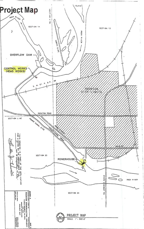
Site map of the Rockton Hydroelectric project, showing the power canal (including head gates and powerhouse) in relation to the city of Rockton and the Rock River.
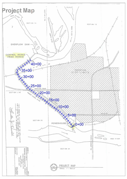
Site layout shown with alignment and stationing used to describe location along canal. Alignment is located on the center line of the power canal, beginning at the powerhouse.
|
The potential for significant damages due to unpredictable flooding creates a need for this investigation. This particular plant has a history of utility trip occurrences, further necessitating this analysis.The purpose of this analysis is to further examine the situation and determine how to prevent over-topping under various flow conditions.
Objectives:
Objectives:
- Compile and organize data relating to power canal and hydroelectric units
- Create a model of the existing power canal to better understand the behavior of the canal under different scenarios, and serve as an instructional tool for operators in anticipating behavior/conditions
- Determine head gate water elevation height threshold that indicates weather eventual over-topping will or will not occur
- Determine locations where over-topping will occur
- Determine times at which over-topping will occur under different flow conditions
- Utilize model to determine if the use of a control device at the wicket gates alone will be sufficient to prevent over-topping of power canal
- Recommend actions that should be taken to prevent over-topping, and justify these with data from the model
|
ECRE has expressed interest in implementing a control device at the wicket gates to automatically re-open them a predetermined amount after a utility trip. In this case, powerhouse gates would open immediately after a utility trip occurs. This would allow water to flow through the powerhouse, and the turbines would be spinning. However, the hydroelectric generators would still need to be manually restarted by an operator, and would therefore be off immediately after the trip event (not generating electricity). If generators are off, the turbines may spin freely up to a certain point. When turbine speed exceeds synchronous speed (RPM), it strains the generator, resulting in damage being done to the equipment. Synchronous speed (rotational speed of the magnetic fields in the units) for the hydroelectric units is 40% of the maximum generation speed. Therefore the maximum amount that wicket gates may be automatically re-opened after a utility trip is 40%. The animation on the right shows a plan view of a wicket gate, intended to clarify how they operate. Control is driven by the two linear hydraulic motors. Red represents high pressure, and blue represents low pressure fluid within each cylinder. The wider the gates are opened, the more water flows to the turbine (in the center), and the more power can be generated. |
 make animated gifs like this at MakeAGif |
